
EKF SLAM
This project involves building an Extended Kalman Filter Simultaneous Localization and Mapping (EKF-SLAM) Algorithm from scratch. This algorithm was then implemented on a TurtleBot3 and tested with cylindrical obstacles. This project was completed using ROS2 Iron and C++.
Source code: GitHub
Video Demo - EKF-SLAM in Simulation
Kinematics
The kinematics library for this projected was developed in C++, and handles calculations involving the kinematics and transformations of the robot. This library can be found under the turtlelib folder in the code. This library contains the following files:
- geometry2d - Handles 2D geometry primitives such as vectors and points.
- se2d - Handles 2D rigid body transformations
- svg - Creates SVG drawings from points, vectors, and coordinate frames
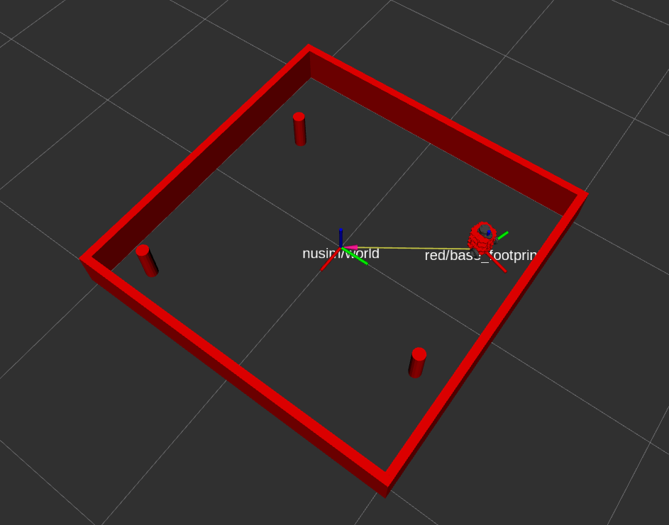
Simulation
A custom simulation environment was designed by using RVIZ. This is handled via a ROS2 Node that simulates robot position and obstacles. The red figure represents the “real” position of the robot. This node simulates the following:
- Robot position (with noise and slippage)
- Lidar sensor data (with noise)
- Obstacle collisions
Robot Control
The robot is controlled by converting incoming Twist messages to wheel commands which directly control the robot wheels. This is done using the custom kinematics library.
The odometry of the robot is calculated using the published JointState messages along with the same kinematics library. This calculation uses the forward kinematics of a standard differential drive robot. The odometry of the robot can be visualized in the simulation environment - it is represented by the blue figure.
Extended Kalman Filter SLAM
Feature-based Extended Kalman Filter SLAM is performed to provide accurate odometry. This algorithim uses two sources of data: Odometry calculations and Fake Sensor Data. In the demo video, the odometry data is calculated without sensor noise, to clearly show how odometry data is affected by collisions. Collisions also simulate how the real robot would drift over time - odometry data would slowly become less accurate.
The Fake Sensor Data represents the data that the LiDAR would output after going through Landmark Detection and Data Association algorithms. The raw LiDAR data is represented by the red dots in the demo video.
EKF SLAM is performed in two main steps:
- Prediction
- Differences in odometry between timesteps are used to predict position
- Inaccurate due to odometry (slipping, noise, drifting over time)
- Correction
- Kalman Gains are calculated by looking at landmark locations
- Robot state is updated using this information
Performance In Simulation
Ground Truth:
x: 0.0 m
y: 0.024 m
θ: -168.070 deg
Odometry:
x: -0.278 m
y: -0.057 m
θ: -168.070 deg
EKF-SLAM:
x: -0.001
y: 0.024
θ: -168.05 deg
Odomotery data had a positional error of 0.289m and no rotational error. Given that collisions were programmed with no rotational component, this data makes sense. The odometry data, with no sensor noise and no rotational collisions, is off linearly but is perfect in terms of the angular position
EKF-SLAM data had a positional error of 0.001 m and a rotational error of 0.02 deg. This data is calculated from both LiDAR and odometry data, so it should be relatively accurate. As expected, EKF-SLAM greatly outperforms odometry data, especially when collisions are involved.