
Mobile Manipulator Simulation
This was the final project of Northwestern University’s ME449 Robotic Manipulation class. This project involves planning a trajectory for a KUKA youBot mobile manipulator to pick up a block at a specified position and orientation, and place the block at a different position and orientation. The KUKA youBot has a 4 mecanum wheels on it’s base with a 5-dof arm.
Source code: GitHub
Video Demo
Trajectory Planning
The trajectory is composed of 8 parts:
- Move the gripper from its initial configuration to a “standoff” configuration above the block
- Move the gripper down to the grasp position
- Close the gripper
- Move the gripper back up to the “standoff” configuration
- Move the gripper to a “standoff” configuration above the final configuration
- Move the gripper to the final configuration of the object
- Open the gripper
- Move the gripper back to the “standoff” configuration
These 8 trajectories were generated using the Modern Robotics Library [1], specifically the ScrewTrajectory() function.
Custom Classes
Rather than storing all of the information in an array, I decided to make a series of custom classes. Although this made calculations slightly more tedious, it was easier to organize all the information, and helped prevent accidentally using the wrong values. The main structure of the classes is:
- RobotState
- Pose
- x, y, phi
- ArmAng
- th1, th2, th3, th4, th5
- WheelAng
- th1, th2, th3, th4
- Pose
- Velocities
- wheelVel
- th1, th2, th3, th4
- jointVel
- th1, th2, th3, th4, th5
- wheelVel
Kinematics
The kinematics of the robot were calculated using by using a first order euler-step approximation of the following:
- Current configuration of the robot (RobotState)
- Current velocities of the robot (Velocities)
- Timestep to use
- Maximum Angular velocities for the wheels and joints
This function returns the next robot state.
To calculate the new position of the robot, I used the following equation 13.10 [2]:
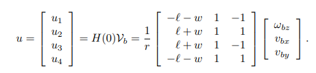
Where:
- r = radius of the wheel
- l = distance from the center of the robot to the center of the wheel, length wise
- w = distance from the center of the robot to the center of the wheel, width wise
- v_b = linear velocities of the robot
- w_b = angular velocity of the robot
- u = angular velocity of each wheel
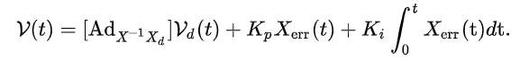
Feedforward Control
Feedforwad control was achieved by using the current end-effector configuration as a function of the current chassis configuration and arm configuraiton. These values come directly from the simulation, so we assume perfect sensors and data. The control law, obtained from equation 13.37 [2], outputs the commanded end-effector twist, which is then converted into wheel and arm joint velocities
Sources
- [1]. Modern Robotics Library, GitHub
- [2]. “Modern Robotics: Mechanics, Planning, and Control” by Kevin Lynch and Frank Park