
Drone Swarm Light Painting
This project uses three Crazyflie Drones to create a long-exposure picture. The camera captures the light emitted by the on-board LEDs over the course of the drones trajectory to create images.
Source code: GitHub
Video Demo
System Overview
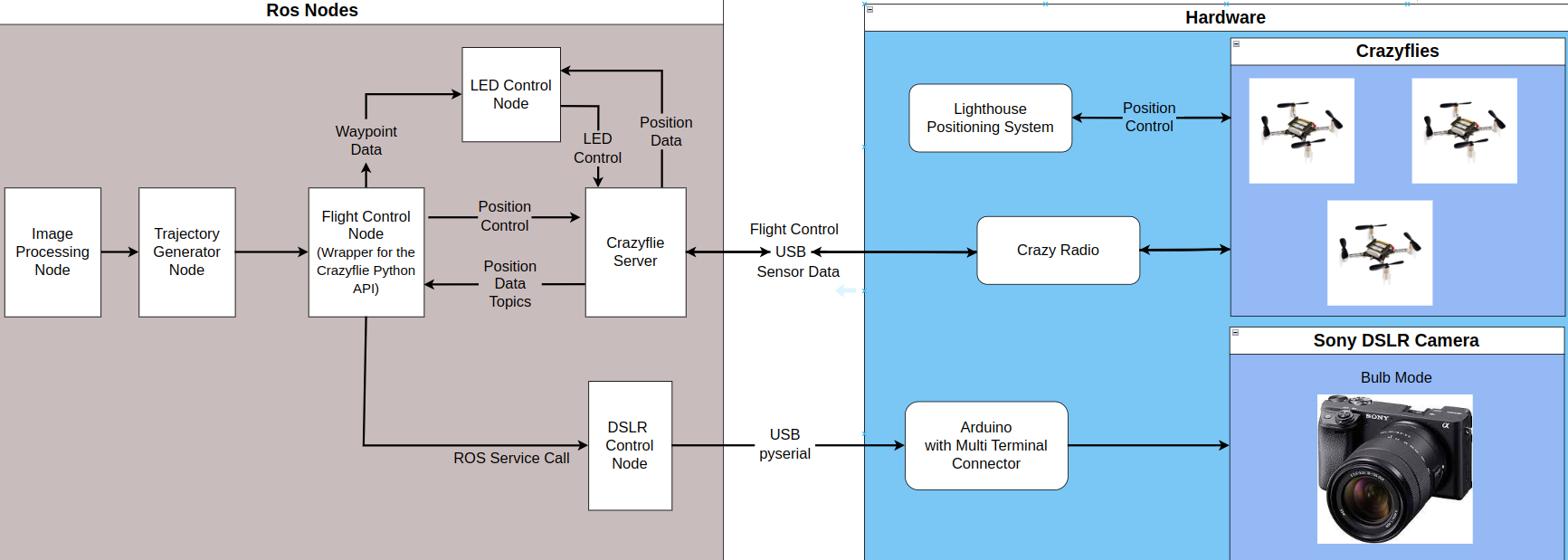
This project interfaces multiple ROS nodes with the Crazyflies, camera, and Crazyflie Server. (Crazyswarm2 Package). These nodes were responsible for shutter control, trajectory generation, and drone control.
Hardware
The following hardware was used in this project:
- Crazyflie 2.1: The drone
- CrazyRadio 2.0: Radio responsible for communication with the drones
- Lighthouse positioning system: Optical positioning system with sub-millimeter precision
- Sony A6400: DSLR Camera for Long Exposure Photography
- Arduino Uno: Controls the DSLR Camera
Camera Control
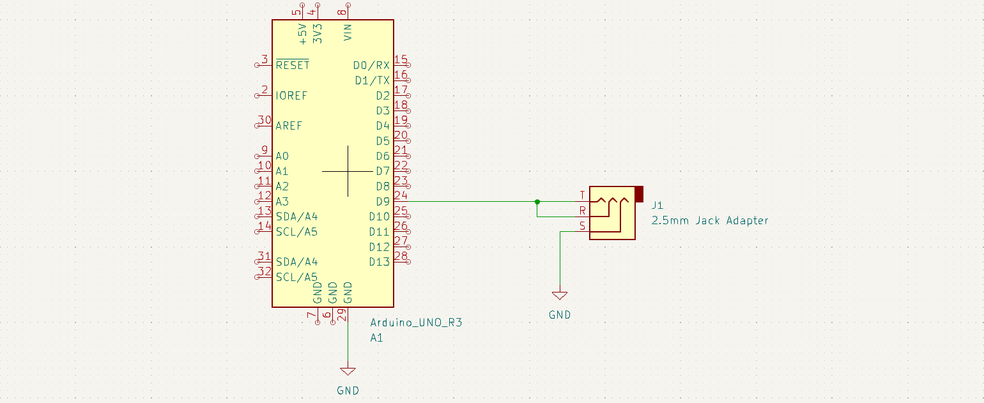
The Sony A6400 DSLR Camera has the Sony Multi-purpose Interface port. This port allows us to control the camera. By using a 2.5mm to Multi-purpose Interface adapter, we can control the camera’s shutter by shorting the tip, ring, and sleeve of the 2.5mm cable. The connections are shown in the schematic below. Pulling the Arduino pin low starts the shutter, while pulling the pin high releases the shutter. This camera supports bulb exposure mode, so the long-exposure shot length can be controlled to match the flight time.
Waypoint Generation
To control the flight path of the drones, I decided to use waypoints that the drone could follow. This was accomplished through the following steps:
- Read the image
- Apply Grayscale and Gaussian Blur
- Use Canny Edge Detection with thresholds of 400 and 500
- Use
numpy.nonzeroto get a list of pixels/points that the edges correspond to - Sort the list of points using a Nearest Neighbor algorithm to create a path that can be followed
- Transform the points into the real-world coordinate frame.
This animation demonstrates the process of generating the waypoints
Light Painting with One Drone
The drone is commanded to navigate through the generated waypoints. In order for the final image to resemble the input image, the onboard LEDs are controlled in one of two ways:
- The LED is turned on when the drone’s position is within a threshold radius of the waypoint
- The LED is turned on when the drone’s position lies on the line formed by the previous waypoint and the next waypoint
This video demo uses the same tree example from earlier, with the LED controller using the first method and a radius of 3cm.
Flight Path Verification
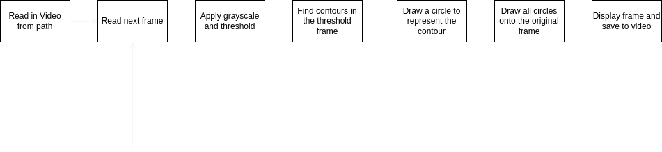
In order to ensure that the drone was flying the correct path, I used OpenCV to help trace the path of the drone in light_painting/script/visualize.py This script was used in both demo videos to help visualize the paths flown.
This diagram shows the logic flow of this script.
Light Painting with Multiple Drones
I modified the ROS2 nodes so that multiple drones can be added by just changing the launch file and the config.yaml file. For the video demo at the top of this page, the following changes were made:
- The URI’s of the additional drones were added to the
light_painting/config/config.yamlfile - I created the
light_painting/launc/light_paint_three.launch.pyfile by duplicating theflightandlednodes multiple times, with different names and colors for each drone